LMD18200T Controllers: pinout, datasheet, circuit, motor driver module,and distinction of LMD18200T and LMD18200T/NOPB
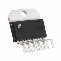
3A mA 13mA mA Motor Drivers 11 42V V 55V V 2
This article will reveal the datasheet , pinout of LMD18200T and other information you want to know.
Catalog
LMD18200T Pinout
LMD18200T CAD Model
LMD18200T Overview
LMD18200T Features
LMD18200T Applications
LMD18200T Alternatives
LMD18200T vs LMD18200T
LMD18200T Block Diagram
LMD18200T Package
Datasheet PDF
Specifications
Product comparison
LMD18200T Pinout
LMD18200T Pin description
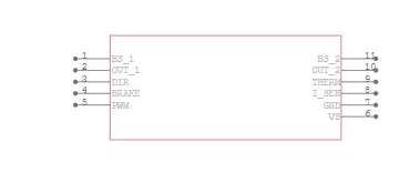
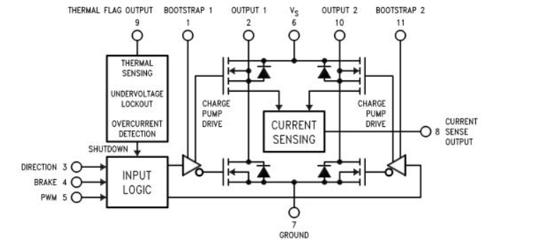
Pin 1, BOOTSTRAP 1 Input: Bootstrap capacitor pin for half H-bridge number 1. The recommended capacitor (10 nF) is connected between pins 1 and 2. Pin 2, OUTPUT 1: Half H-bridge number 1 output.
Pin 3, DIRECTION Input: This input controls the direction of current flow between OUTPUT 1 and OUTPUT 2 (pins 2 and 10) and, therefore, the direction of rotation of a motor load.
Pin 4, BRAKE Input: This input is used to brake a motor by effectively shorting its terminals. When braking is desired, this input is taken to a logic high level and it is also necessary to apply logic high to PWM input, pin 5. The drivers that short the motor is determined by the logic level at the DIRECTION input (Pin 3): with Pin 3 logic high, both current sourcing output transistors are ON; with Pin 3 logic low, both current sinking output transistors are ON. All output transistors can be turned OFF by applying a logic high to Pin 4 and a logic low to PWM input Pin 5; in this case, only a small bias current (approximately −1.5 mA) exists at each output pin.
Pin 5, PWM Input: How this input (and DIRECTION input, Pin 3) is used is determined by the format of the PWM Signal.
Pin 6, VS Power Supply Pin 7, GROUND Connection: This pin is the ground return, and is internally connected to the mounting tab.
Pin 8, CURRENT SENSE Output: This pin provides the sourcing current sensing output signal, which is typically 377 μA/A.
Pin 9, THERMAL FLAG Output: This pin provides the thermal warning flag output signal. Pin 9 becomes active low at 145°C (junction temperature). However, the chip won't turn off, though, until the junction temperature reaches 170°C.
Pin 10, OUTPUT 2: Half H-bridge number 2 output.
LMD18200T CAD Model
Symbol
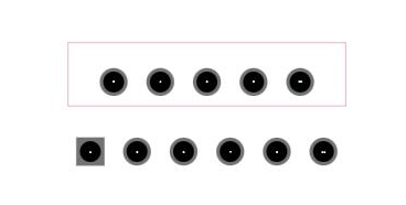
Footprint
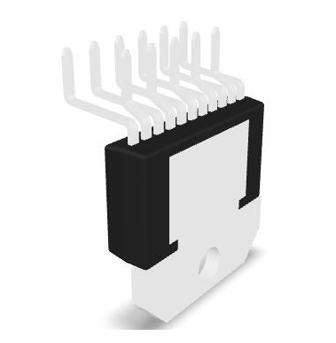
3D-model
LMD18200T Overview
A 3A H-Bridge created for motion control applications is the LMD18200T. The LMD18200T is constructed utilizing a multi-technology process that integrates DMOS power devices with bipolar and CMOS control circuits on a single monolithic structure. The LMD18200T is perfect for driving DC and stepper motors and can handle peak output currents of up to 6A. The implementation of a novel circuit allows for low-loss output current sensing.
LMD18200T features
Delivers Up to 3A Continuous Output
Operates at Supply Voltages Up to 55V
Low Ros(ON) Typically 0.33Q per Switch at 3A
TTL and CMOS Compatible Inputs
No“Shoot-Through" Current
Thermal Warning Flag Output at 145°C
Thermal Shutdown (Outputs Off) at 170°C
Internal Clamp Diodes
Shorted Load Protection
Internal Charge Pump with External Bootstrap Capability
LMD18200T Applications
DC and Stepper Motor Drives
Position and Velocity Servomechanisms
Factory Automation Robots
Numerically Controlled Machinery
Computer Printers and Plotters
LMD18200T Alternatives
LMD18201T
LMD18200T/NOPB
Product comparison
LMD18200T vs LMD18200T/NOPB
There is no so much distinction between LMD18200T and LMD18200T/NOPB, the difference existed in their packaging. Check out this tablet.
Part No. | LMD18200T/NOPB | LMD18200T |
Description
| IC H BRIDGE 3A 55V TO220-11 | 3A 55V H-BRIDGE |
Classification
| Semiconductor & Actives | Motor Drivers |
Reference Price(USD)
| $16.150 | 16.431 |
Number of Pins
| - | 11 |
Number of Channels
| - | 2 |
Output Voltage
| - | 3.00w |
Output Voltage
| - | 55.0v |
Supply Voltage (DC)
| - | 12.0v(min) |
Output Current
| EAR99 | - |
Output Current
| - | 3.00A |
Number of Outputs
| - | 2 |
Packaging
| Tube | Rail |
Lead-Free Status
| PB Free | Contains lead |
RoHS
| RoHS Compliant | Non-Compliant |
Product Lifecycle Status
| Unknow | Active |
LMD18200T Block Diagram
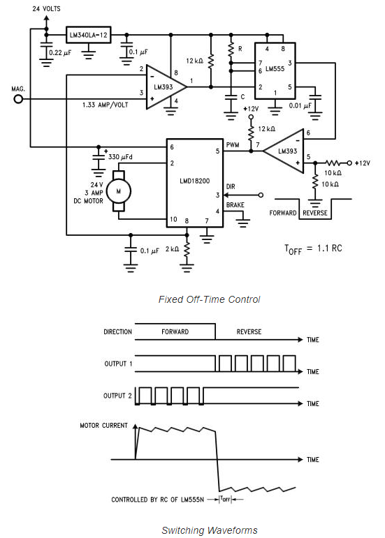
LMD18200TApplication circuit
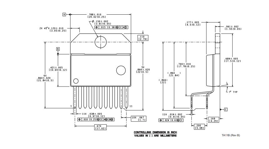
LMD18200T Dimensions
Datasheet PDF
Please DOWNLOAD the datasheets and manufacturer documentation for the LMD18200T .
Specifications


